Products

What sets this fermented bean curd paste apart from other varieties?

Our fermented bean curd paste stands out from other varieties for several reasons:

  1. Unique Flavor Profile: Our fermented bean curd paste is crafted using a proprietary recipe that results in a distinctive and complex flavor profile. It balances the natural richness of fermented soybeans with savory, umami notes and a hint of tanginess, creating a truly unique taste experience.
  2. Premium Ingredients: We source only the highest quality ingredients for our fermented bean curd paste, ensuring superior flavor and freshness. From non-GMO soybeans to carefully selected seasonings and spices, every component is chosen with care to deliver exceptional quality and taste.
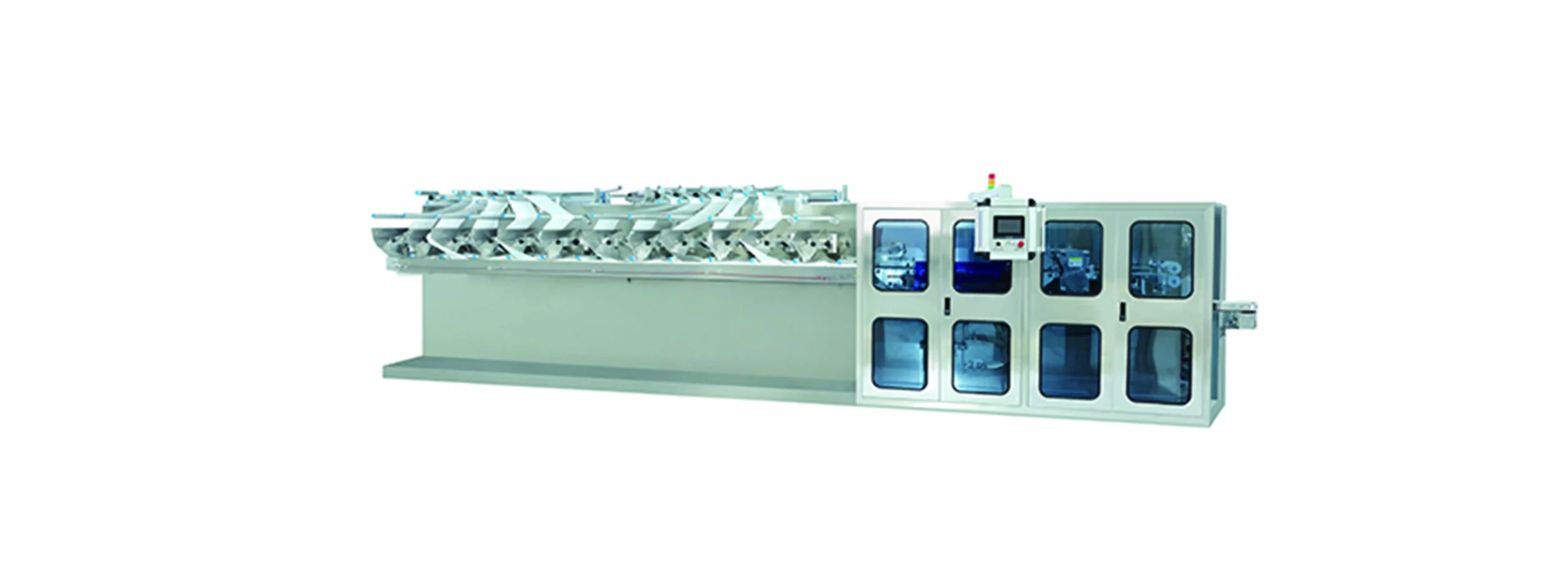
  3. Traditional Production Methods: Our fermented bean curd paste is made using traditional fermentation techniques that have been perfected over generations. This time-honored approach allows the flavors to develop naturally and ensures authenticity and depth of flavor in every batch.
  4. Versatility: Our fermented bean curd paste is incredibly versatile and can be used in a wide range of dishes, from stir-fries and marinades to sauces and dressings. Its bold flavor adds depth and complexity to both traditional Asian recipes and modern fusion cuisine.
  5. Quality Assurance: We take great pride in the quality and consistency of our fermented bean curd paste. fermented bean curd paste  Our production facilities adhere to stringent quality control standards, and each batch undergoes rigorous testing and inspection to ensure that it meets our exacting standards for flavor, texture, and safety.

Overall, our fermented bean curd paste is a testament to our commitment to excellence and innovation in Asian condiments. Its unique flavor, premium ingredients, traditional production methods, versatility, and quality assurance set it apart as a standout choice for discerning chefs and home cooks alike.


What are the three kinds of pipe fittings?

Pipe fittings are vital components utilized to connect, reroute, control, and adjust the flow of liquids or gases within piping systems.

There are lots of types of pipe fittings offered, yet they can typically be classified into three main teams based on their function and building:

Socket Bonded, Threaded, and Butt Weld Fittings:

Outlet Bonded Fittings: Socket weld fittings are used for little pipe sizes and low-pressure applications. They have a socket at one end into which the pipeline is inserted and welded for a safe connection. Typical sorts of outlet weld installations consist of elbow joints, tees, combinings, and unions.
Threaded Fittings: Threaded fittings have threaded ends that enable them to be screwed onto the ends of pipelines or other installations without welding. They are typically utilized for small to tool pipeline sizes and reduced to moderate stress applications. Sorts of threaded installations consist of arm joints, tees, nipple areas, and caps.
Butt Weld Fittings: Butt weld installations are used for bigger pipe sizes and high-pressure applications. They are welded directly onto the ends of pipelines using a butt welding procedure, which produces a strong, leak-proof connection. Butt weld fittings include arm joints, tees, reducers, and caps.

Flanged Fittings:

Flanged fittings have level surfaces with screw holes that enable them to be bolted onto flanged ends of pipelines or equipment. They provide a strong, stiff link that is resistant to movement and resonance. Flanged installations are commonly made use of in high-pressure and high-temperature applications, such as oil and gas pipelines, chemical handling, and power plants. Types of flanged installations include flanged arm joints, tees, reducers, and blind flanges.


Compression Fittings:

Compression fittings are used to link pipelines or tubes utilizing compression force to produce a watertight seal. They include a compression nut, ferrule, and body that press the tubes or pipe versus a securing surface to develop a limited link. Compression fittings are frequently made use of in plumbing and fluid circulation systems for water, gas, and air. They are simple to set up and dismantle without the requirement for special tools or soldering.
These are the three primary sorts of pipe fittings generally used in piping systems. Each kind has its own advantages, constraints, and applications, and the choice of fitting depends on aspects such as pipeline size, pressure rating, temperature, material compatibility, and installment needs.

How do refractory ceramic fiber perform in terms of thermal insulation?

Refractory ceramic fibers (RCF) are known for their excellent thermal insulation properties, making them widely used in various high-temperature applications.

Here’s how RCF performs in terms of thermal insulation:

  1. Low Thermal Conductivity: RCF exhibits low thermal conductivity, meaning it has a high resistance to heat transfer. This property allows RCF to effectively insulate against high temperatures, minimizing heat loss or gain in industrial processes and equipment.
  2. High Temperature Resistance: RCF can withstand extreme temperatures, typically up to 2300°F (1260°C) or higher depending on the specific grade and composition. This high-temperature resistance makes RCF suitable for use in furnaces, kilns, boilers, and other thermal processing equipment.
  3. Uniform Thermal Performance: RCF offers uniform thermal performance, providing consistent insulation across its entire structure. This uniformity helps maintain stable temperatures in thermal systems, preventing hotspots or temperature differentials that could affect process efficiency or product quality.
  4. Low Heat Storage: RCF has low heat storage capacity, meaning it absorbs minimal heat energy when exposed to high temperatures. This property allows RCF to quickly dissipate heat, reducing the risk of thermal damage or overheating in industrial applications.
  5. Resistance to Thermal Shock: RCF exhibits good resistance to thermal shock, meaning it can withstand rapid changes in temperature without cracking or spalling. This property is crucial in applications where thermal cycling or sudden temperature fluctuations occur, refractory ceramic fiber  such as in kiln linings or furnace walls.
  6. Lightweight and Insulating: RCF is lightweight compared to traditional refractory materials such as brick or castable refractories. Despite its low density, RCF provides excellent insulation, making it an attractive option for applications where weight reduction and thermal efficiency are important considerations.
  7. Chemical Stability: RCF demonstrates good chemical stability, resisting degradation or corrosion when exposed to chemical agents, gases, or molten metals at high temperatures. This chemical resistance enhances the longevity and reliability of RCF insulation in harsh industrial environments.
  8. Flexible and Versatile: RCF is available in various forms, including blankets, boards, papers, and textiles, allowing for flexibility and versatility in insulation design and installation. These different forms can be tailored to specific application requirements, providing customized thermal insulation solutions.

Overall, refractory ceramic fibers offer exceptional thermal insulation performance, combining high-temperature resistance, low thermal conductivity, uniformity, and versatility. These properties make RCF ideal for insulating industrial equipment, process vessels, piping systems, and other high-temperature environments, helping to improve energy efficiency, safety, and productivity in various industries.

What factors should be considered when selecting ceramic fire boards for a specific application?

When selecting ceramic fire boards for a specific application, several factors should be considered to ensure optimal performance and suitability. These factors include:

  1. Temperature Requirements: Consider the maximum temperature that the ceramic fire board will be exposed to in the application. Choose a board with a temperature rating that exceeds the maximum temperature expected in the environment.
  2. Fire Resistance: Evaluate the fire resistance properties of the ceramic fire board, including its ability to withstand exposure to flames and heat without igniting or releasing harmful gases. Look for boards with high fire ratings and certifications from recognized testing organizations.
  3. Thickness and Density: Determine the appropriate thickness and density of the ceramic fire board based on the specific requirements of the application. Thicker and denser boards typically offer higher levels of insulation and fire protection.
  4. Dimensional Stability: Assess the dimensional stability of the ceramic fire board, particularly if it will be exposed to temperature fluctuations or thermal cycling. Choose a board that maintains its shape and integrity under varying conditions to prevent warping, cracking, or delamination.
  5. Chemical Resistance: Consider the chemical environment in which the ceramic fire board will be used and ensure that it is resistant to corrosion, acids, alkalis, and other chemicals present in the surroundings.
  6. Moisture Resistance: Evaluate the moisture resistance properties of the ceramic fire board, especially if it will be exposed to humidity, water, or steam. Choose a board with low water absorption and good resistance to moisture-related damage.
  7. Physical Properties: Consider the physical properties of the ceramic fire board, ceramic fire board  such as strength, durability, and hardness. Select a board that can withstand handling, installation, and any mechanical stresses encountered in the application.
  8. Installation Requirements: Determine the installation method and requirements for the ceramic fire board, including cutting, shaping, fastening, and sealing. Ensure that the board is compatible with the installation techniques and materials used in the application.
  9. Compatibility with Other Materials: Verify that the ceramic fire board is compatible with other materials used in the application, such as adhesives, sealants, and insulation. Avoid materials that may cause chemical reactions or compatibility issues when in contact with the board.
  10. Regulatory Compliance: Ensure that the ceramic fire board complies with relevant industry standards, regulations, and building codes applicable to the specific application and location. Look for boards with certifications from recognized testing organizations.
  11. Cost and Budget: Consider the cost of the ceramic fire board and ensure that it aligns with the project budget while meeting the required performance and safety standards. Evaluate the long-term value and benefits of the board compared to its initial cost.

By carefully considering these factors and conducting thorough research, you can select the most suitable ceramic fire board for your specific application, ensuring optimal performance, safety, and durability.

Where can I find the baby set bedding for purchase?

You can find baby bedding sets for purchase at various retailers, both online and in-store. Here are some options to consider:

  1. Online Retailers: Websites such as Amazon, Walmart, Target, Bed Bath & Beyond, and Buy Buy Baby offer a wide selection of baby bedding sets in different styles, colors, and designs. You can browse their websites, read product descriptions, and compare prices and customer reviews to find the right set for your needs.
  2. Baby Specialty Stores: Specialty baby stores, both online and brick-and-mortar, often carry a curated selection of baby bedding sets. Examples include Pottery Barn Kids, Crate & Kids, Land of Nod, and Babies “R” Us (if available in your area).
  3. Department Stores: Major department stores like Macy’s, Nordstrom, and Kohl’s may also carry baby bedding sets in their baby or nursery departments. Check their websites or visit their stores to see their offerings.
  4. Local Boutiques: Explore local baby boutiques or specialty stores in your area that cater to parents and caregivers. baby set bedding  They may carry unique or handmade baby bedding sets that you won’t find elsewhere.
  5. Online Marketplaces: In addition to Amazon, online marketplaces such as eBay and Etsy offer a wide range of baby bedding sets from various sellers. You can find both new and used sets, as well as custom-made or personalized options on these platforms.
  6. Manufacturer Websites: Some baby bedding manufacturers sell their products directly through their own websites. If you have a specific brand or style in mind, you can visit the manufacturer’s website to see their current offerings and make a purchase.

When shopping for baby bedding sets, be sure to consider factors such as safety, quality of materials, ease of cleaning, and adherence to recommended safe sleep guidelines. Additionally, check the dimensions of the bedding to ensure it fits your baby’s crib or bassinet properly.

How is the wet wipes automatic packaging machine speed adjusted to suit different production requirements?

The speed of a wet wipes automatic packaging machine can be adjusted to suit different production requirements. The adjustment process typically involves settings and controls that operators can modify based on the specific needs of a production run.

Here are common methods for adjusting the speed of a wet wipes automatic packaging machine:

  1. Variable Frequency Drive (VFD):
    • Many automatic packaging machines, including those for wet wipes, utilize Variable Frequency Drives (VFDs). A VFD allows operators to adjust the speed of the machine’s motor by changing the frequency of the electrical power supplied to it. This provides precise control over the machine’s speed, allowing for adjustments to match different production requirements.
  2. Human-Machine Interface (HMI) Controls:
    • The machine is equipped with an HMI, a user-friendly interface that allows operators to interact with and control various aspects of the packaging process. Through the HMI, operators can access settings related to speed control and make adjustments accordingly.
  3. Speed Adjustments on Conveyor Systems:
    • In a wet wipes packaging machine, conveyor systems play a crucial role. These systems often come with adjustable speeds that can be manually set or controlled through the machine’s interface. Operators can adjust the conveyor speed to synchronize with the overall packaging process.
  4. Programmable Logic Controller (PLC) Programming:
    • PLCs are commonly used in automated packaging machines. The machine’s PLC can be programmed to include different speed profiles for various production requirements. By selecting the appropriate program, operators can set the machine to run at different speeds.
  5. Inverter Control:
    • Inverters are used to control the speed of electric motors in packaging machines. wet wipes automatic packaging machine  Operators can use inverter controls to adjust the speed based on the requirements of the specific wet wipes packaging job.
  6. Adjustable Timing and Dwell Settings:
    • Some wet wipes packaging machines allow operators to adjust the timing and dwell settings for specific operations, such as sealing or cutting. By modifying these settings, operators indirectly influence the overall speed of the machine.
  7. Product-Specific Settings:
    • For different wet wipes products with varying sizes, quantities, or packaging requirements, the machine’s settings can be adjusted to accommodate these specific parameters. This may include adjusting the speed to ensure proper filling, sealing, and packaging of different wet wipes configurations.
  8. Operator Training:
    • Proper operator training is crucial for effectively adjusting machine speeds. Operators should be familiar with the machine’s controls, interface, and the impact of speed adjustments on the overall packaging process.
  9. Sensors and Feedback Systems:
    • Automatic packaging machines often incorporate sensors and feedback systems that provide real-time data on the production process. Operators can use this feedback to make informed decisions about adjusting the machine speed to optimize performance.
  10. Production Planning and Scheduling:
    • Adjustments to the machine speed may also be influenced by production planning and scheduling. Operators may set the machine to run at different speeds based on the production volume, deadlines, or specific order requirements.

It’s essential to follow the manufacturer’s guidelines and recommendations for adjusting the speed of the wet wipes automatic packaging machine. Regular maintenance and calibration of the machine components also contribute to maintaining consistent and accurate speed adjustments over time.

How is the hot melt glue for wet wipe cover lid machine cleaned and sanitized between different production runs?

Cleaning and sanitizing the hot melt glue system for a wet wipe cover lid machine between different production runs is crucial to maintain product quality, hygiene, and equipment efficiency. Here is a general guide on how this process can be carried out:

Cleaning Process:

  1. Shutdown Procedure:
    • Ensure that the wet wipe cover lid machine is shut down properly and that all moving parts are stationary.
  2. Empty the Glue Reservoir:
    • If the machine has a glue reservoir or tank, empty it of any remaining hot melt glue from the previous run. Follow the manufacturer’s instructions for proper disposal or recycling of the unused glue.
  3. Purge the Glue Lines:
    • Run the machine in a purge mode to push out any remaining glue in the glue lines. This helps prevent contamination between different glue formulations.
  4. Remove Glue Applicator Components:
    • Depending on the machine design, remove the glue applicator components such as nozzles, hoses, and filters. Clean these components thoroughly using an appropriate cleaning solution.
  5. Clean Reservoir and Lines:
    • Clean the glue reservoir and glue lines with a suitable cleaning solution recommended by the glue manufacturer. This helps remove any residual glue and contaminants.
  6. Inspect and Replace Components:
    • Inspect all glue applicator components for wear, damage, or clogs. Replace any damaged or worn parts to ensure optimal performance in the next production run.
  7. Use Cleaning Solution Compatible with Glue:
    • Select a cleaning solution that is compatible with the hot melt glue being used. Some hot melt glues may have specific cleaning requirements, and using the wrong cleaning agent could affect performance.

Sanitization Process:

  1. Sanitizing Solution:
    • Prepare a sanitizing solution suitable for use with the hot melt glue system. This solution should have antimicrobial properties to eliminate any potential bacteria or contaminants.
  2. Apply Sanitizing Solution:
    • Apply the sanitizing solution to all the glue applicator components, glue reservoir, hot melt glue for wet wipe cover lid machine  and glue lines. Ensure thorough coverage to sanitize all surfaces that come into contact with the glue.
  3. Allow Sufficient Contact Time:
    • Follow the recommended contact time specified by the sanitizing solution manufacturer. This ensures that the sanitizing agent effectively eliminates any microbes or contaminants.
  4. Rinse and Dry:
    • Rinse all components thoroughly with clean water to remove any residual sanitizing solution. Allow the components to dry completely before reassembling the glue applicator system.
  5. Run Purge Cycle:
    • Run a purge cycle with the machine to clear out any remaining water or cleaning solution from the glue system. This ensures that the system is ready for the next production run.
  6. Verify Cleanliness:
    • Perform a visual inspection to verify that all glue applicator components are clean and free from any residues. Confirm that the glue system is in optimal condition for the next production run.
  7. Record Keeping:
    • Maintain detailed records of the cleaning and sanitization process, including the cleaning agents used, contact times, and any replacement of components. This documentation supports traceability and quality control.

Always refer to the specific guidelines provided by the machine and glue manufacturers for the proper cleaning and sanitization procedures. Additionally, comply with any industry regulations or standards related to hygiene and equipment maintenance in the production of wet wipe cover lids.

How are excavator bottom roller designed to withstand shock loads and sudden impacts?

Excavator bottom rollers are crucial components of the undercarriage system, and they must be designed to withstand shock loads and sudden impacts associated with heavy-duty excavation and construction work.

Here are several design considerations employed to enhance the ability of excavator bottom rollers to withstand such loads:

  1. Material Selection:
    • High-strength materials, such as alloy steels or other wear-resistant alloys, are commonly used for manufacturing bottom rollers. These materials provide the necessary strength and durability to withstand shock loads.
  2. Heat Treatment:
    • Heat treatment processes, such as quenching and tempering, are applied to improve the hardness and toughness of the material. This enhances the resistance of the bottom roller to wear, abrasion, and impact.
  3. Forged Construction:
    • Bottom rollers are often forged rather than cast, as forging provides a more uniform and dense grain structure, resulting in increased strength and impact resistance.
  4. Roller Design:
    • The overall design of the roller, including the shape and thickness of the roller shell, is optimized to distribute loads evenly and resist deformation under impact.
    • Reinforced sections or additional material may be strategically placed in areas prone to high stress and impact.
  5. Sealed Bearings:
    • High-quality, sealed bearings are used in the assembly to protect against contaminants such as dirt, China excavator bottom roller for sale  debris, and water. This not only ensures smooth rotation but also prevents premature wear due to external elements.
  6. Internal Lubrication Systems:
    • Some bottom rollers feature internal lubrication systems that deliver grease to critical components, reducing friction, and enhancing the roller’s ability to handle shock loads.
  7. Precision Machining:
    • The manufacturing process involves precision machining to ensure accurate dimensions and proper alignment. This helps in maintaining the integrity of the roller and its ability to handle loads without excessive wear.
  8. Impact-Resistant Coatings:
    • Applying specialized coatings to the surface of the bottom roller can enhance its resistance to impact and abrasion. Hard-facing or wear-resistant coatings may be utilized for this purpose.
  9. Reinforced Rim Sections:
    • The rim sections of the bottom roller, which come into direct contact with the track links, are often reinforced to withstand the impact of the track links during operation.
  10. Finite Element Analysis (FEA):
    • FEA is employed during the design phase to simulate and analyze the structural behavior of the bottom roller under different loading conditions. This helps identify areas that may be prone to stress concentration and allows for design optimization.
  11. Testing and Validation:
    • Prototypes and production units undergo rigorous testing to validate their performance under real-world conditions. This includes simulated shock loads and impact tests to ensure that the bottom roller meets or exceeds specified durability standards.

By incorporating these design features and manufacturing processes, excavator bottom rollers can be engineered to withstand the shock loads and sudden impacts encountered in demanding construction and excavation environments. Regular maintenance and timely replacement also contribute to ensuring the long-term durability of these components.

What advancements have been made in the use of sensors and monitoring technology in excavator sprocket ?

However, I can provide some general trends and possibilities that could be applicable to excavator components, including sprockets:

  1. Load Sensors:
    • Integration of load sensors on sprockets can help monitor the actual loads experienced during operation. This data can be used for optimizing machine performance, preventing overloading, and improving efficiency.
  2. Temperature Monitoring:
    • Incorporating temperature sensors on sprockets allows for real-time monitoring of heat levels. Elevated temperatures may indicate excessive friction or inadequate lubrication, helping to prevent premature wear and failure.
  3. Wear Monitoring and Predictive Maintenance:
    • Advanced sensors and monitoring systems can be designed to track the wear and tear of sprocket teeth. By analyzing this data, predictive maintenance models can predict when maintenance is needed, reducing downtime and extending the lifespan of the sprocket.
  4. Vibration Sensors:
    • Vibration sensors can be employed to detect irregularities in the operation of the sprocket. Unusual vibrations may indicate misalignment, imbalance, or other issues that can lead to premature wear or failure.
  5. Wireless Connectivity:
    • Integration of wireless communication technologies allows data collected by sensors on the sprocket to be transmitted to a central monitoring system. This facilitates real-time monitoring and remote diagnostics, enabling timely intervention and maintenance.
  6. Condition Monitoring Systems:
    • Comprehensive condition monitoring systems can be implemented to monitor multiple aspects of the excavator, China excavator sprocket for sale  including sprocket performance. These systems can provide operators and maintenance personnel with detailed insights into the health of critical components.
  7. IoT (Internet of Things) Integration:
    • The adoption of IoT technologies enables excavator components, including sprockets, to be connected to the internet. This connectivity allows for continuous data streaming, remote monitoring, and analysis of performance metrics.
  8. Embedded RFID (Radio-Frequency Identification):
    • RFID tags or sensors embedded in sprockets can provide unique identification and maintenance history. This aids in tracking individual components, managing inventory, and ensuring that replacement sprockets are compatible and properly maintained.
  9. Advanced Analytics and Machine Learning:
    • The use of advanced analytics and machine learning algorithms can analyze large datasets generated by sensors. This enables the identification of patterns, trends, and anomalies, leading to more accurate predictions and better-informed maintenance decisions.
  10. Environmental Sensors:
    • Sensors that monitor environmental conditions, such as humidity and dust levels, can help assess the impact of external factors on sprocket performance and guide maintenance practices.

It’s essential to check with equipment manufacturers and industry sources for the latest developments, as technology in the construction and heavy machinery sector is continually evolving. Manufacturers often introduce new features and technologies to enhance the efficiency, reliability, and safety of their equipment.

How can the machine be protected from power surges, and what measures are in place to safeguard electronic components?

Protecting a CO2 laser machine from power surges is crucial to safeguard its electronic components and ensure reliable operation. Power surges, which involve sudden and temporary increases in electrical voltage, can potentially damage sensitive electronic parts.

Here are measures to protect the machine and its electronic components from power surges:

  1. Voltage Stabilizers:
    • Install voltage stabilizers or voltage regulators to maintain a consistent and stable power supply. These devices help mitigate fluctuations in voltage and protect against both surges and sags.
  2. Surge Protectors:
    • Use surge protectors or surge suppressors to intercept and divert excess voltage away from the machine. Place surge protectors in the power supply line to absorb and dissipate voltage spikes.
  3. Uninterruptible Power Supply (UPS):
    • Employ uninterruptible power supply systems. A UPS provides a short-term power source during outages and acts as a buffer against power surges, allowing the machine to shut down gracefully in the event of a prolonged outage.
  4. Isolation Transformers:
    • Use isolation transformers to electrically isolate the laser machine from the main power source. Isolation transformers can help prevent the transmission of power surges to the machine.
  5. Power Conditioning Equipment:
    • Invest in power conditioning equipment designed to filter out electrical noise and maintain a clean power supply. This can contribute to the longevity of electronic components.
  6. Automatic Voltage Regulators (AVR):
    • Install automatic voltage regulators to regulate and stabilize the incoming voltage. AVRs adjust the voltage to within acceptable limits, protecting electronic components from overvoltage.
  7. Circuit Breakers and Fuses:
    • Install appropriate circuit breakers and fuses in the electrical circuit. mini co2 laser engraving machine  These devices can trip or blow in the event of a power surge, preventing damage to the machine’s components.
  8. Grounding:
    • Ensure that the CO2 laser machine is properly grounded. Grounding helps to dissipate excess electrical energy safely and reduces the risk of damage from power surges.
  9. Regular Electrical System Checks:
    • Periodically check the electrical system for any signs of wear, loose connections, or faulty wiring. Address any issues promptly to prevent potential electrical hazards.
  10. Emergency Power-Off (EPO) System:
    • Implement an Emergency Power-Off (EPO) system that allows for the quick shutdown of the machine in case of emergencies or detected power irregularities.
  11. Isolation of Sensitive Electronics:
    • Isolate sensitive electronic components within the machine from the main power supply to minimize the risk of damage during power surges.
  12. Lightning Protection:
    • Install lightning protection systems, especially in areas prone to lightning strikes. Lightning can cause severe power surges that may damage electronic equipment.
  13. Quality Power Cords and Connectors:
    • Use high-quality power cords and connectors that meet safety standards. Cheap or damaged cords can compromise the effectiveness of surge protection measures.
  14. Regular Equipment Inspections:
    • Conduct regular inspections of the laser machine’s electrical components. Look for signs of damage, overheating, or any abnormalities that may indicate a power-related issue.
  15. Education and Training:
    • Train machine operators and maintenance personnel on the importance of power surge protection and the proper use of protective devices.
  16. Manufacturer Recommendations:
    • Follow the manufacturer’s recommendations regarding power supply requirements and surge protection. Manufacturers often provide guidelines to optimize the machine’s performance and lifespan.

Implementing a combination of these measures will help protect the CO2 laser machine from power surges and enhance the overall reliability of its electronic components. It’s essential to tailor these measures to the specific requirements and recommendations provided by the machine’s manufacturer.